Verify process effectiveness, observe internal phenomena and prevent defects before the first pour
Shrinkage defects
Residual stresses
Macro and microporosity
Hot & Cold cracks
Deformations and warping
Micro‑Structure
Build a digital twin of your sand mold in minutes. Skip physical trial castings entirely
.svg)
Slash material and labor expenses with accurate process validation
.svg)
Prevent porosity, shrinkage cavities, and cracks before tooling

Test gating, risers and pouring parameters in a digital twin environment
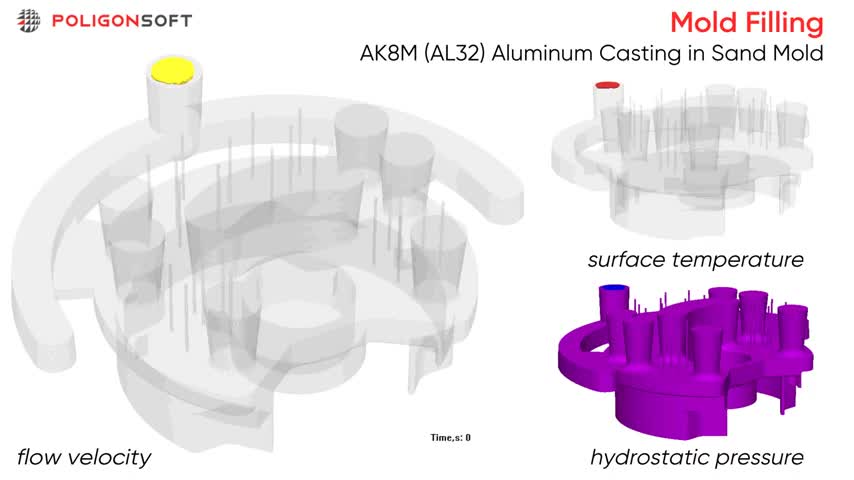
Euler Flow Solver lets you simulate mold filling at constant or variable pouring rates through one or multiple ingates. It outputs velocity fields, flow vectors, metal temperature, and hydrostatic pressure, revealing slow‑flow zones, turbulence, air entrapment, and misrun risk.
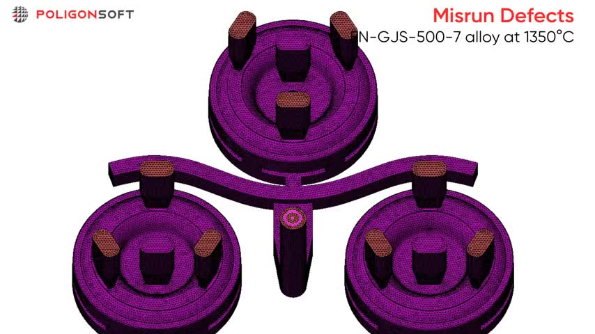
The filling simulation includes full heat‑transfer modelling via the Fourier solver, continuously updating temperature‑dependent viscosity and surface tension. This real‑time feedback pinpoints flow‑front freeze‑off and accurately predicts misrun / cold‑shut locations.
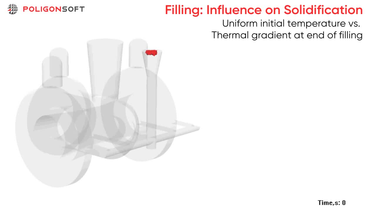
The temperature map captured at the end of filling is handed off as the initial condition for the solidification module, giving the solver a precise thermal baseline that sharpens shrinkage‑porosity and hot‑spot predictions.
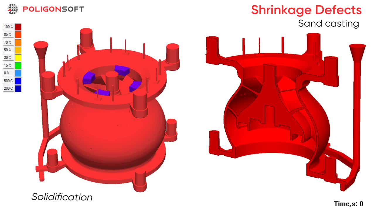
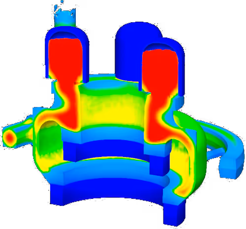
The Fourier solidification solver models transient heat exchange with mold components and the surrounding environment to calculate local cooling and feeding rates. It predicts thermal hotspots, shrinkage cavities, and porosity, delivering detailed temperature and defect maps.
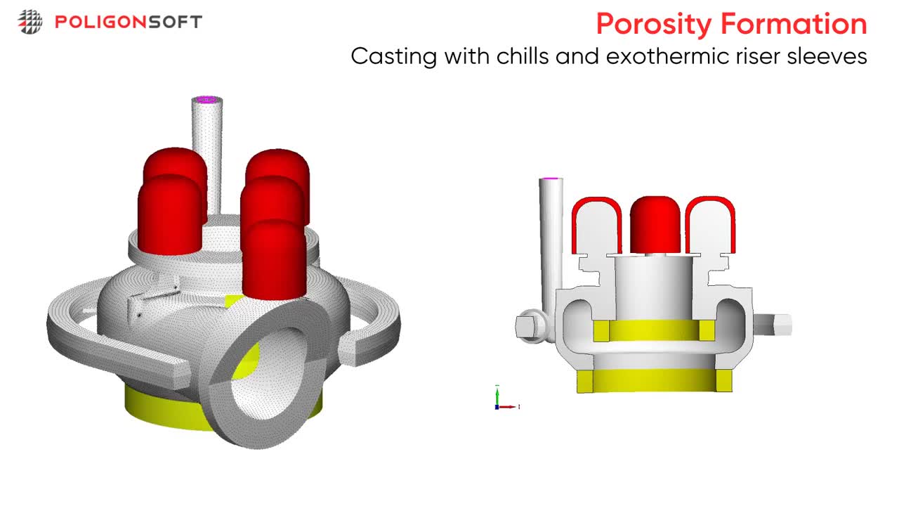
PoligonSoft models exothermic sleeves with effective thermal properties and latent‑heat release to capture their heat boost. It also simulates chills, insulators and mold materials, showing how all elements interact to improve feeding and limit shrinkage.
We continually compare simulation output with real foundry castings, refining our algorithms whenever gaps appear. Results are also benchmarked against rival software to keep prediction accuracy at an industry‑leading level.
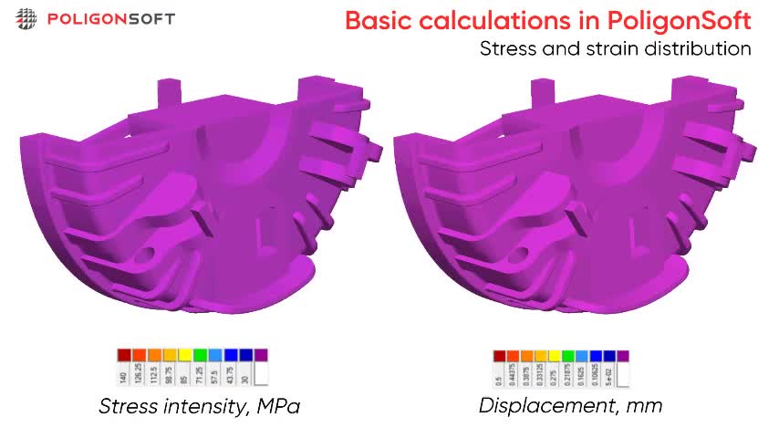
The Hooke stress solver computes residual strain and stress‑intensity maps, nodal displacement vectors that reveal warping, and a matrix of potential failure nodes. These fields let you visualize distortion, assess safety margins, and adjust machining allowances or feeding‑system layout before production..
The crack module flags nodes where local stress intensity meets or exceeds the temperature‑dependent tensile strength defined in the alloy data. This damage criterion maps crack initiation and hot tearing zones so you can adjust design or process early.
Load STEP/IGES, auto‑heal geometry, and generate a high‑quality triangular mesh in ≤ 5 min.
Select alloy grade, binder system, sand properties, and exothermic sleeves from the built‑in database.
Enter melt temperature, constant or variable pour rate, mold pre‑heat and ambient cooling.
Launch Euler Flow, Fourier Solidification, and Hooke Stress solvers in a single run on up to 24‑core multi‑threaded CPUs.
Visualize velocity and temperature fields, generate porosity and hot‑spot maps, plus residual‑stress plots.
Modify gating, risers or cooling paths and re‑run fast iterative simulations until targets are met

The case shows the optimization of the sand casting process for a helicopter cabin frame. The objective was to lower process cost by reducing expensive thermal insulating sleeves and simplifying mold assembly.

Helicopter Window Frame produced by Russian Helicopters holding
Material: Magnesium alloy ML5pch
Mold: Cold‑setting mixtures (Alpha‑Set)
Risers: FOSECO exothermic sleeves
Pouring temperature: 760 °C
Casting block mass: 55.3 kg
Casting mass: 9.8 kg
The previous casting technology provided acceptable quality but was associated with high costs, increased labor requirements, and a high rate of defects. Analysis revealed insufficient process stability.
Due to the nearly simultaneous solidification of the casting and feeder system, even minor variations in process parameters, such as molten metal temperature, could result in shrinkage porosity forming within the casting.

Distribution of porosity greater than 1% and shrinkage defects

To achieve a defect‑free casting and reduce overall cost, the gating system was reworked. Vertical feeders were replaced with one lateral feeder without thermal insulation, and the central feeder concept was retained. This change improved directional solidification and reduced the need for costly insulating sleeves. As a result, porosity stayed within the accepted manufacturing limits.
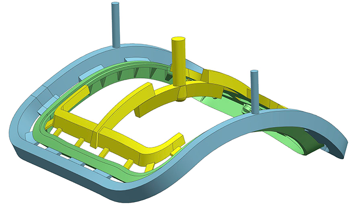
Left: Optimized gating design. Right: Porosity (>1%) and shrinkage defects.

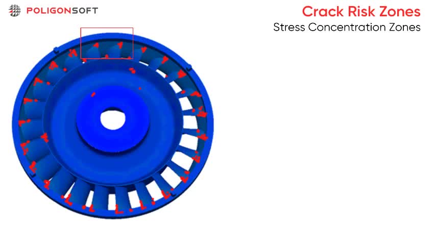
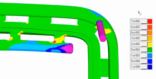
Solidification simulation showed no shrinkage‑related defects. During the trial casting, however, cracks appeared at the junctions with the feeding system. This triggered a dedicated residual‑stress analysis, which revealed elevated residual stresses and local plastic deformation in those areas, confirming the need for geometry and process adjustments.

Left: Cracks detected on the trial casting at the junctions with the feeding system.Plastic deformation intensity map from PoligonSoft simulation.
Right: Plastic deformation intensity map from PoligonSoft simulation.

The analysis identified the cause of cracks at the casting–feeder junctions. An improved version was developed, featuring reduced residual stress levels and eliminating the formation of cracks. The optimized design was successfully implemented and is currently in use for helicopter production.
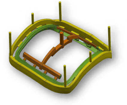
Left: Final sand mold and gating design.
Right: Plastic deformation intensity map.
The Siemens stator ring was produced as an experimental sand casting using a no‑bake mold. The initial trial revealed misrun defects and isolated porosity near one riser. PoligonSoft simulation was used to analyze metal flow and solidification, identify the root causes, and optimize the gating and riser design.

Incomplete filling of the inner teeth.
Porosity near one of the risers.
The original gating layout used three risers and one cylindrical riser with an exothermic sleeve. Simulation showed that a slight increase in pouring temperature would resolve the misrun defect in the inner teeth. Shrinkage‑related defects, however, could not be fixed by temperature alone since they resulted from improper directional solidification. The risers froze too early and stopped feeding the hot spot.


Cross‑section of the temperature field in the porosity area shows the formation of an unfed hot spot.

The zones where porosity reaches the casting surface predicted by the simulation coincide with the experimental results.
To restore directional solidification and eliminate porosity, the feeding system was reconfigured:
a new exothermic feeder was added at the hot‑spot location to supply liquid metal during the last stages of solidification.
the existing exothermic feeder was resized and paired with a ceramic insulator to extend its feeding time.
iron chillers and a chromite rod were introduced to accelerate solidification in sound regions and force metal flow toward the risers.
After these changes the stator ring filled completely and solidified without macro or microporosity. Trial castings confirmed the part to be defect‑free and ready for production use.


Insulator (new)
Iron chillers
(new)
Chromite rod
(new)
Exothermic sleeve
(new size)
Exothermic feeder to eliminate the area of macro and microporosity (new)
Verification of the reliability of PoligonSoft’s hot‑crack prediction model on a full‑scale industrial valve body sand casting.

Alloy: 20GL steel
Mold: clay‑bonded green sand
Exothermic sleeves: FOSECO Kalminex
Pouring temperature: 1600 °C
Аlow‑velocity field and temperature map captured continuous metal delivery into the cavity

Flow velocity field

Temperature distribution
The solidification dynamics study showed that the feeding system works correctly and no hot spots are formed. The porosity study confirmed that no area inside the casting exceeds 1 % porosity; isolated shrinkage appears only at the riser necks, indicating that the feeding system works correctly in the rest of the part.

Hot spots analizis

Porosity 1 % and above

Deformation (Left View)

Deformation (Top View)

Hot Crack Indicator

Result Verification
PoligonSoft’s stress–strain model predicts hot- and cold-crack formation with high probability. Accurate simulation of modern casting processes requires accounting for the contact interaction between the casting and the mold, because this interaction is often the root cause of cracking.
Being able to predict cracks at the design stage greatly reduces the time and cost needed to fine-tune and optimise the process.

Practical workshops and webinars cover casting techniques, offering theoretical and applied sessions to master simulations.

Complete reference covering software interface, simulation settings, analysis tools, and practical recommendations.

Peer‑reviewed document outlines algorithms, validation data, and industrial cases supporting simulation accuracy and reliability.


.svg)
.svg)
.svg)

.svg)