For a quick start working with PoligonSoft, a simple problem - the thermal calculation of casting an aluminum alloy into a metal chill mold will be solved step by step. To do it, use a prepared file with a finite element mesh (or GM - geometric model) located in PoligonSoft folder. The meshing process will not be covered in this chapter. Also, this section does not consider the process of preparing material properties, heat transfer parameters and other necessary calculation conditions. This is described in detail in the Databases section. In this example, we will use ready data files.
This chapter consists of the following sections:
Case Setup
The file required for the calculation is located in the % Poligon%\Examples\PoligonTest folder and has the name Pompa.g3d. You need to copy the entire PoligonTest folder to another location, for example, C:\PoligonTest, and perform all subsequent actions there.
Geometу Preparation in the Master Module
The Master preprocessor is started by the Master button in the PoligonSoft shell (see the Module Calls section). At the first start, the module window looks like in fig. below.
The first thing to do is load the GM file. To do this, press the button  (1) on the toolbar at the top of the window. The Loading Options window will open, in which you should select the POLIGONSOFT file type (2). In this case, the list (3) will indicate the units "Meters" in which the GM mesh is recorded (these settings are set by default). Then press the OK button (4). In the Open Geometry File dialog go to the C:\PoligonTest folder, select the Pompa.g3d file and click the Open button. The file will be loaded and the model of the casting in the form will be displayed in the working window of the Master module (see the figure below).
The rotation of the model on the screen is carried out with the left mouse button, the movement of the model - with the right mouse button, the zooming of the model - with the mouse wheel.

View of the Master module window at the first start
Most of the window is occupied by the area in which the loaded GM is displayed (see the figure below). In our case, the model consists of a casting (red) and a mold (blue). For clarity, the mode of showing the section of the form is turned on (for more details, see the Model Display Modes section). The mold consists of a Die, which is visible in the figure, and a Core, which is inside and is not visible.

Master module with loaded model
For the correct calculation of the shrinkage porosity, the model must be oriented in the coordinate system of the PoligonSoft system in such a way that its vertical position coincides with the Y axis directed upwards. The model orientation can be checked by pressing the  Reset Rotations button or the Ctrl+W keyboard shortcut (see the figure below). In this case, the coordinate system is set to the "Front view" position (the Y axis is directed upwards, the Z axis is directed towards the user). As shown in the figure, the position of the casting and the mold corresponds to the technological process, which means that their orientation in the PoligonSoft coordinate system is set correctly.

Checking the orientation of the geometric model
Now it is necessary to set the basic parameters of the technological process. To do this, press the  Start Simulation and Parameters button or keyboard shortcut Ctrl+R. A window will open in which you should enter the following data (see figure below).

Start Simulation and Parameters window
In the Start Simulation and Parameters window you need to fill in the table on the General tab. This is the basic parameters required to run any calculation.
- Alloy Temperature. Click in the cell opposite the parameter and enter the pouring alloy temperature 650 °C.
- Mold Temperature. Click in the cell opposite the parameter and enter the initial die and core temperature 20 °C.
- Ambient Temperature. Click in the cell opposite the parameter and enter an ambient temperature 20 °C.
- Alloy Properties File. Double-click in the cell opposite the parameter. Click the
 button at the end of the line. In the Alloy Properties File dialog, find the AL-2.bd file in the C:\PoligonTest folder and load it. The file name will appear in the parameter line (see the figure above).
- Mold Properties File. Double-click in the cell opposite the parameter. Click the
 button at the end of the line. In the Mold Properties File dialog, find the Die Casting.bdf file in the C:\PoligonTest folder and load it. The file name will appear in the parameter line (see the figure above).
 - Heat Transfer File. Double-click in the cell opposite the parameter. Click the
 button at the end of the line. In the Heat Transfer File dialog, find the Die Casting.afo file in the C:\PoligonTest folder and load it. The file name will appear in the parameter line (see the figure above).
 - Thread Count. Click in the cell opposite the parameter and enter the number of processor cores used for the calculation. It is highly recommended that you enter a number that does not exceed the number of physical processor cores.
Go to the Flow tab and make sure the Enable Flow Model option is unckecked (see Figure below). This time, only solidification and porosity calculations will be run. For information on how to prepare the model for a filling calculation, see the Mold Filling section.

Flow Tab
Go to the Solidifcation tab and make sure that the parameters are set as shown in fig. below. These are the default settings and generally do not need to be changed.

Solidifcation Tab
Go to the Porosity tab and make sure that the parameters are set as shown in fig. below. These are the default settings and generally do not need to be changed. On this tab, you only need to set the Alloy Properties File parameter (highlighted in the figure below). Double-click in the cell opposite the parameter. Click the button  at the end of the line. In the Alloy Properties File dialog, find the AL-2.fil file in the C:\PoligonTest folder and load it. The file name will appear in the parameter line.
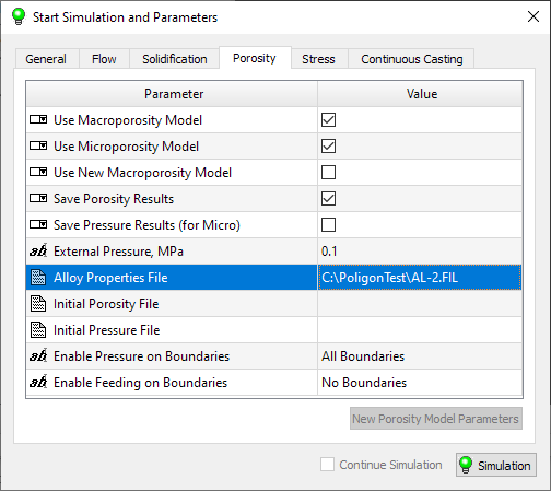
Porosity Tab
Go to the Stress tab and make sure the Enable Stress Model option is off (see figure below). This time, only solidification and porosity calculations will be run. For information on how to prepare the model for stress analysis, see the Stresses and Deformations section.

Stress Tab
Now all the parameters for die casting process calculating are set, it remains to apply them to the geometric model. Close the Start Simulation and Parameters window.
In PoligonSoft, it is customary to distinguish between two types of volumes: casting and mold. At the same time, the mold can consist of different materials (in our case, it is a die mold and a sand core). To distinguish volumes within the same type (Mold), each volume is assigned a unique index by which the required material properties are assigned to the volume. Visually, the types of volume indices differ in color.
The assignment to the volumes of the geometric model of the corresponding types and indices is carried out in the model tree, which is located on the left. Using the checkboxes opposite the lines in the tree, you can disable and enable the display of GM volumes in the graphic area of the Master module. Double-clicking on a line in the tree or on a volume in the graphics area opens the Volume Parameters dialog (see the figure below), here you can assign the type and index to the selected volume. It is necessary to assign the casting body type "Casting" and index 1, to the body of the die mold body - type "Mold" and index 2 (steel 9Cr2MoV), to the core body - type "Mold" and index 4 (sand mixture according to the Alphaset process). Editing the parameters of each volume is completed by pressing the OK button.
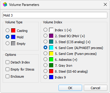
Volume Parameters Window
To see the model colored in the colors of the volume indices, click the Volume Index Mode button on the toolbar below (see the figure below).
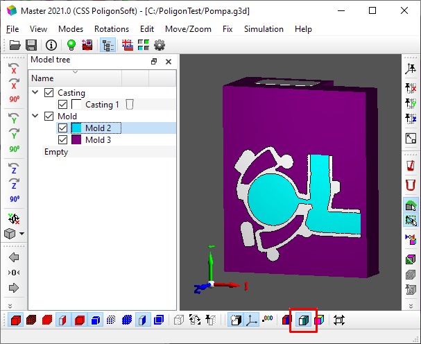
Volume Index Mode
Finally, the internal and external boundaries of the GM must be defined. At the stage of GM loading, PoligonSoft automatically determines the "casting-mold", "casting-medium" and "mold-environment" boundaries . These boundaries, as well as volumes, are assigned indices: 1, 17 and 18, respectively. For the considered example, this is quite enough. For more information about the indices of boundaries, volumes and their meaning, see the Basic concepts: Volumes, Types, Indexes section.
To save the work done, you can click  Save Geometry button or the keyboard shortcut Ctrl+S. When the module finishes, it is also suggested to save the geometry file and all data. The functions of the Master module are discussed in more detail in Preparing the Modeling Area section .
Simulation
To start the calculation, you need to open the Start Simulation and Parameters window and click the Simulation button under the data table (see the figure below).
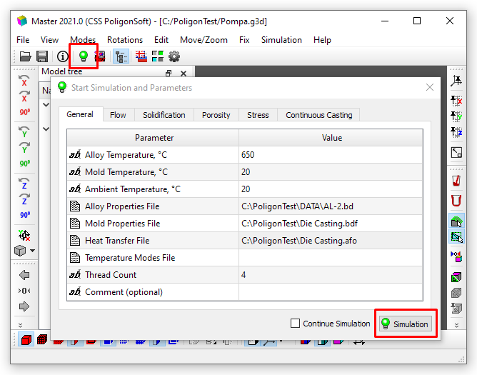
Run Simulation
First, you should save the entire project to the C:\PoligonTest folder, overwriting the previously saved file. Then the calculation will start, its state is reflected in the DOS console (see the figure below). To calculate the solidification, record results messages are displayed.
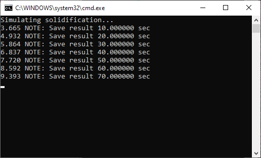
Calculation progress
When the calculation is finished, the console will display the message “Simulating solution successfully finished” (see the figure below). The console can be closed.
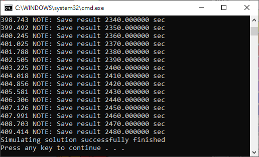
End of calculation
Viewing Results
The calculation results can be viewed and analyzed both during the execution of the calculation and after its completion in the Mirage postprocessor. It is launched by the Mirage button in the PoligonSoft shell (see the Module Calls section). When you start it for the first time, you may need to customize the appearance of the main window. To do this, in the Window View menu, you need to sequentially select all the items responsible for displaying toolbars.
Results for analysis are loaded by commands from the File menu or using the buttons on the toolbar at the top of the window. The result files are located in the C:\PoligonTest folder.
 |
Open Temperature button loads files of the * .CST type containing phase and temperature fields into the module. You can also use the keyboard shortcut Ctrl+T. |
 |
OpenPorosity button loads *.P3D files containing porosity fields into the module. You can also use the keyboard shortcut Ctrl+R. |
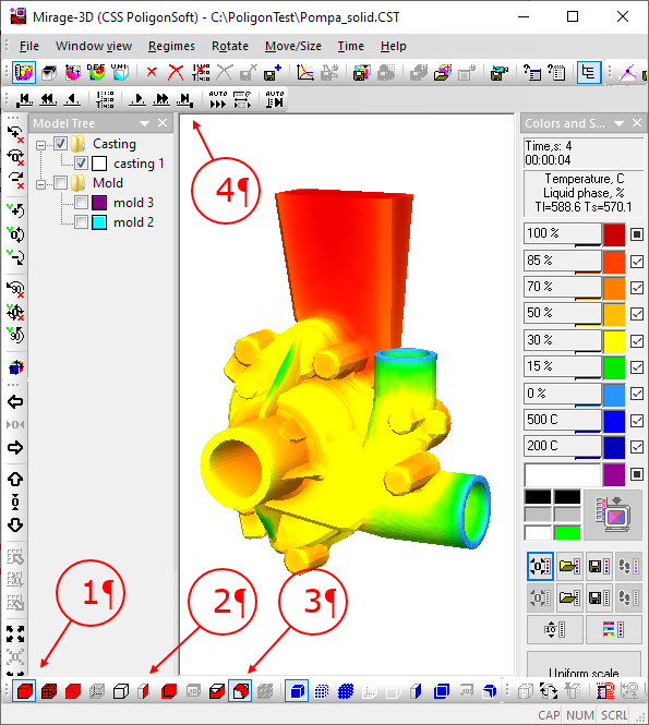
After loading (see the figure below), you can view the results in the solid body mode (1), section in an arbitrary plane (2) and isosurface (3). Viewing field changes in time is carried out using the Time Contro Bar (4).
Working with the Mirage postprocessor is described in more detail in the chapter Viewing Results.


.svg)
.svg)
.svg)

.svg)